Talkbox
The idea of building the Talkbox came as a request from my friend Aleix Bou. I knew the sound and I’ve seen vintage footage of people using this weird sound effect where people talks and sings through a tube. Some cool examples can be found by Stevie Wonder or more recently by Byron Chambers aka “Mr. Talkbox” as in Bruno Mars 24K Magic intro. The appearance of Roger Troutman doing some demonstration on TV is one of my favorites.
I always believed that this particular sound effect was some sort of vocoder where the sound is picked up directly at the mouth thought the tube. After some quick research I realized that the Talkbox it’s much simpler than the Vocoder and actually works the inverse direction. The basic idea is just to feed the sound to the mouth, replacing the vocal cords as sound generator and shape the tube’s incoming sound with the mouth. Some basic description of how the talkbox works and many more related resources can be found at GFWORKS.
Compression Driver and PA
Looking at similar DIY projects I found the work by Mosivers a good start point since he used the Monacor KU-516 compression driver in combination with a small integrated PA. The Monacor KU-516 seems to be a good choice for a replacement of the old and discontinued Electro Voice “1823M” and “1824M” Compression Drivers. It is recommended also by the Japanese experts of GFWORKS. Ideally, the driver should cover the vocal frequency range, which is not that easy when talking about small speakers and compression drivers. The Monacor KU-516 provides still a relatively wide bandwidth covering a range of 160-6500 Hz. The Kemo M033N PA drives an output power of 18W for a 4Ω impedance and a supply of 20V. The power supply chosen for the project is 12V and the Monacor KU-516 impedance is of 16Ω and Power rating (RMS) of 50W so technically it will be under amplified. Still, given the application, considering than the compression driver should go directly into a person’s mouth, we don’t need to reach very high levels. A few breadboard prototype tests revealed how the selected PA provides enough/safe amplification.
Project design
Technically, with the PA, the compression driver and a tube, the Talkbox cloud be already assembled and finished. But in order to have a more complete unit, I decided to add two more sections. First a preamp, because the input level could vary substantially. The keyboard seems to be the more popular instrument to use with the Talkbox. But other instruments/sound sources like a guitar, smartphone or a computer could potentially be used as well. So it could come handy to have this extra input boost for a more flexible input. Secondly, a tone control section. This might be less of a requirement but a wish feature, but many commercial Talkbox sound effects out there include one and I found it a very basic but effective way of shape the timber of the signal. Still the main idea of this project was just to do a very simple design reusing available well-knowns designs for the different sub-circuits.
Preamplifier and Tone Control Design
There is different opinions out there about the placement of the preamps and tone control stages within the audio chain. It seems to depend in quite some factors and really depending on the specific application. Some argue that placing the tone control before the gain stage could sound a bit more noise while the inverse configuration can’t work perfectly also at certain frequency ranges. I won’t go into this discussion and for the sake of simplicity I decided to just place them with the pre-amp just before the tone control circuit.
Starting with the tone control, I selected the design of the guys of Electrosmash where they adapted the full Big Muff Pi guitar pedal circuit. I liked this circuit because of its effectivity and simplicity as they mention. One pot just to control a RC low-pass/CR high-pass filtering network.
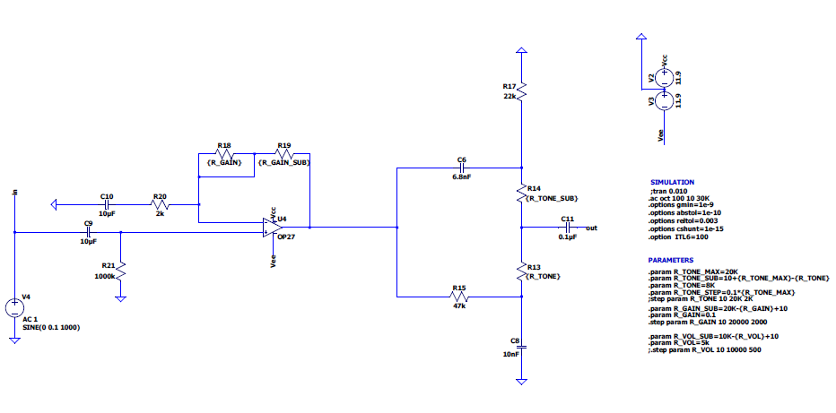
For the preamplifier I just went for the non-inverting amplifier configuration using the popular TL072 op-amp. I set the input/output resistor ratio gain stage initially to boost the input signal by 10dB gain. Still, as the tone control section has as about 7-8dB loss, I added +10dB to the gain stage. So while the intermediate gain (a the input of the tone control circuit) is +20dB, this becomes about 12dB gain at the tone control output.
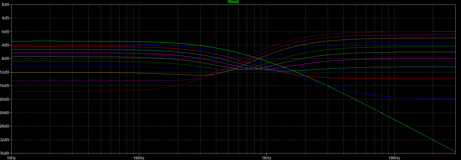
To verify and fine tune some of the component values, I simulated this part of the project in LTSPICE. Se below the schematic and frequency response (with fixed gain) when sweeping the tone control potentiometer. We can clearly see the low-pass/high-pass behavior which corresponds to the left and right-most position of the potentiometer respectively. While ideally the flattest response should correspond to the exact middle position of the potentiometer we can see how this is practically not achieved and normally the flattest response should be around the middle plus slight to the right rotation.
Prototyping
At this point it was a good moment to do some trials and try to build a prototype of the entire project before moving to PCB design. Most parts worked quite easily due to the simplicity of the project. Still I had some noise issues when connecting the power amplifier. Most of the annoying “humm” noise seemed to come from the PA input where it seems to be a common issue. The general recommendation seems to be to use as short as possible connection between circuit output and PA input. This combined with a shielded cable for that particular connection looked like a much better approach and got rid of the loud “humm” noise.
PCB Design
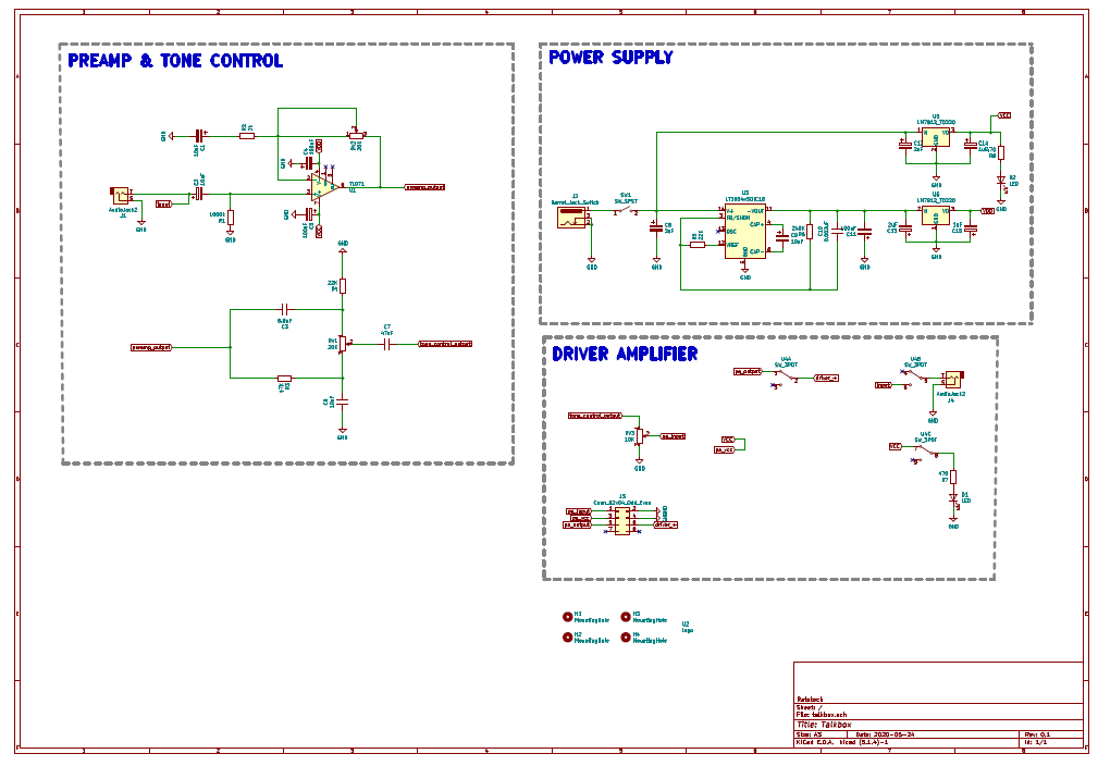
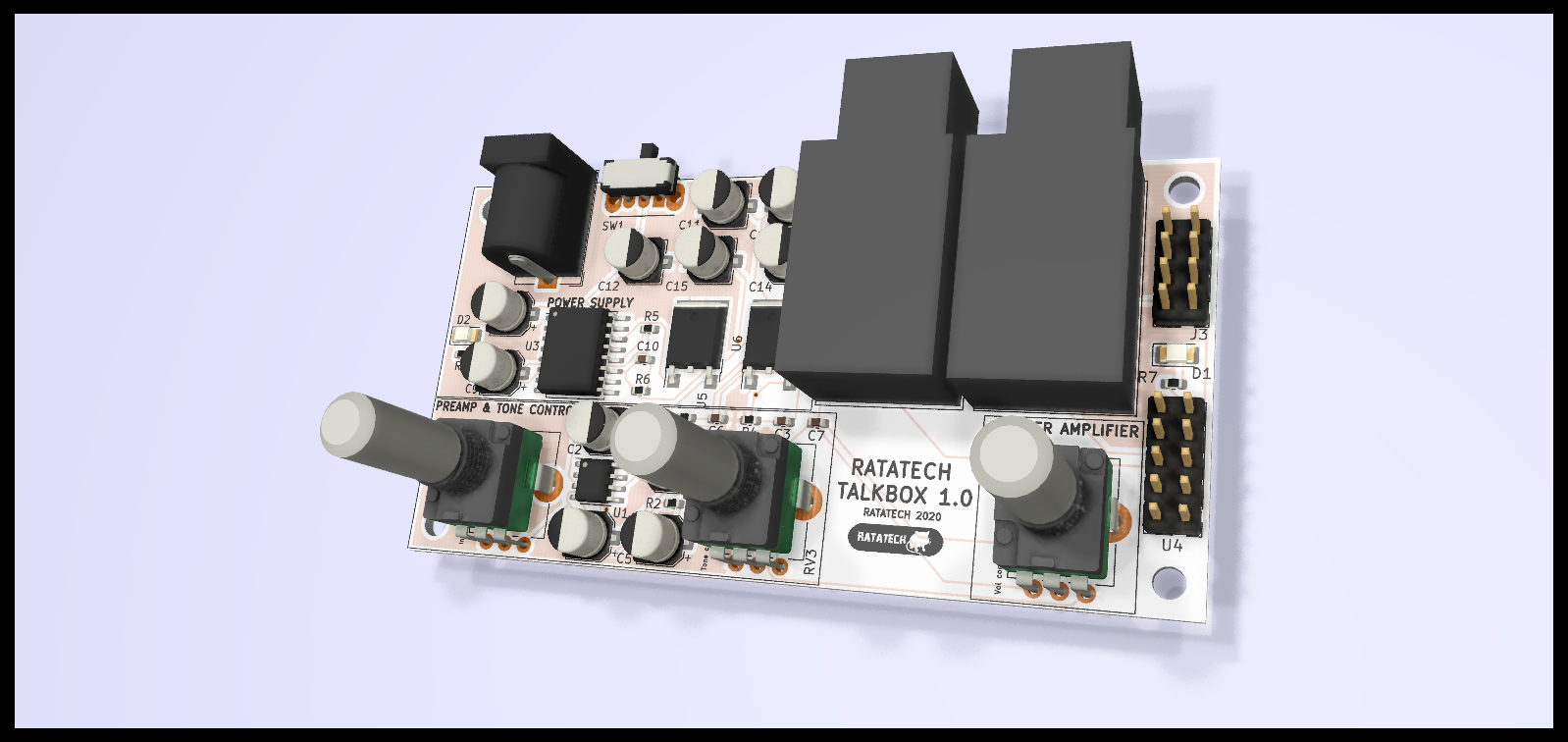
After simulation and breadboard prototyping I moved to KiCad for the PCB design. I divided the whole PCB in three main parts, first the Preamp and Tone Control circuits, the power supply and finally the driver amplifier. The Preamp & Tone Control part it’s kind of the same as already displayed on the LTSpice schematics. The power supply is based on the LT1054 switched-capacitor voltage converter plus a couple of linear voltage regulators LM7812/LM7912. Then on the driver amplifier part all the wiring and switching with the 3PDT footswitch is done. There is essentially no “driver amplifier” circuitry on the PCB more than the routing of the signals itself with the Kemo M033N power amplifier which feeds the compression driver. See the complete schematic and layout KiCad files on the github project.
PCB fabrication
After the PCBs arrived from the fab-house, I started the final step on the PCB fabrication, a few moments of the whole process can be observed on the group of images below. First fixing carefully the PCB with the stencil and applying the copper paste on top. Right after I populated the components on it’s corresponding positions ready to be soldered. Finally the soldering was achieved using a cooking hot plate which worked quite well this time due to the small size of the PCB. Larger PCBs tend to bend a little bit making that all the surface of the PCB not being in contact with the hot plate. In that case some components can remain unsoldered.